FH-01-A | 1.0 m-class configurations
Listed flood heights ≤ 1.0 m. Support requirements vary with clear width; widths over 6 m require project review.

Rapid-install modular flood protection for industrial buildings, underground spaces, logistics routes and wide openings. FH-01-A and FH-01-B use mechanical clamps to secure panels and compress EPDM seals, replacing conventional bolted fixings. Select the model and supports against the clear opening width and design flood height.
FH-01-A / FH-01-B · November 2026 A/B model revision
Discuss your project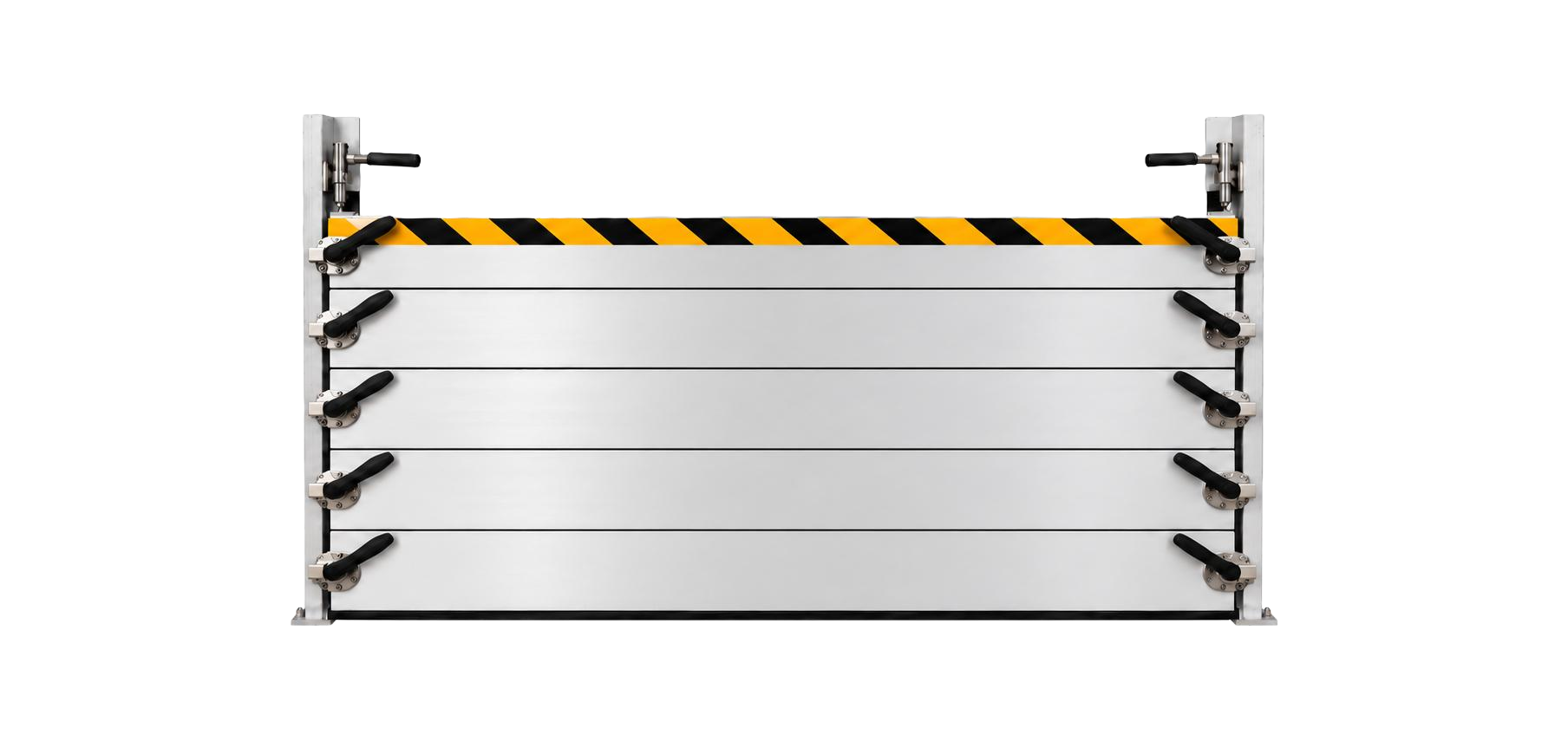
Source: the November 2026 A/B model revision in Chinese and English. Model, width, height and supports are paired configurations, not a universal maximum height for every opening. Design life is not a warranty term or a maintenance-free commitment.
SYSTEM ADVANTAGES
Mechanical clamps replace individual bolted fixings during deployment for faster assembly and repeatable installation. Permanent tracks still require secure anchorage; the catalogue specifies a lever bar for clamp installation.
Panels and tracks form continuous flood barriers. Aluminium alloy, stainless steel and zinc alloy fittings combine strength, corrosion resistance and ease of handling. Confirm the configuration for the project.
Multiple EPDM seals and a dedicated bottom seal work with mechanical compression to control leakage paths under hydrostatic pressure. Confirm watertightness against a valid report for the selected configuration.
A straightforward structure and storage rack simplify component management. Regular cleaning, seal checks and moving-part maintenance support long-term reliability.
A/B MODEL AND SUPPORT SELECTION
FH-01-A covers listed configurations up to 1.0 m; FH-01-B offers listed configurations at 1.2 m or 1.8 m. The table follows the revised catalogue. Use each row as a matched model, width, height and support arrangement.
Listed flood heights ≤ 1.0 m. Support requirements vary with clear width; widths over 6 m require project review.
3 m × 1.2 m can use no supplemental support; 3–6 m × 1.2 m uses a top compression post; 3 m × 1.8 m uses an intermediate post and diagonal bracing.
| Model | Clear opening width | Design flood height | Support configuration |
|---|---|---|---|
| FH-01-A | ≤ 3 m | ≤ 1.0 m | No supplemental support |
| FH-01-A | > 3 m – 6 m | ≤ 1.0 m | Top compression post |
| FH-01-A | > 6 m | ≤ 1.0 m | Intermediate posts and diagonal bracing, subject to project review |
| FH-01-B | 3 m | 1.2 m | No supplemental support |
| FH-01-B | 3–6 m | 1.2 m | Top compression post |
| FH-01-B | 3 m | 1.8 m | Intermediate post and diagonal bracing |
The catalogue lists both a 3 m × 1.2 m Model B arrangement without supplemental support and a 3–6 m × 1.2 m arrangement with a top compression post. At the 3 m boundary, confirm supports against the selected design and installation drawings. Do not generalise the listed 3 m width to every width ≤ 3 m. Other dimensions or conditions require review.
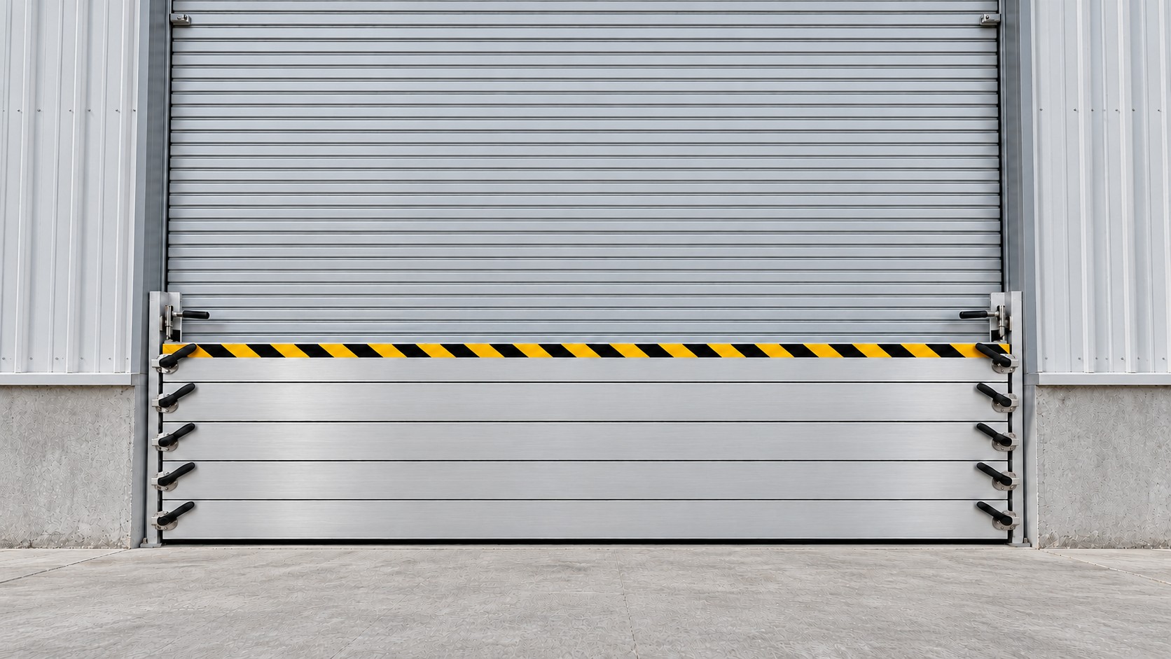
A ≤ 1.0 m / B 1.2 m
Model A: width ≤ 3 m, height ≤ 1.0 m. Model B: width 3 m, height 1.2 m. No top compression post, intermediate post or diagonal bracing; tracks and anchorage still require proper installation.
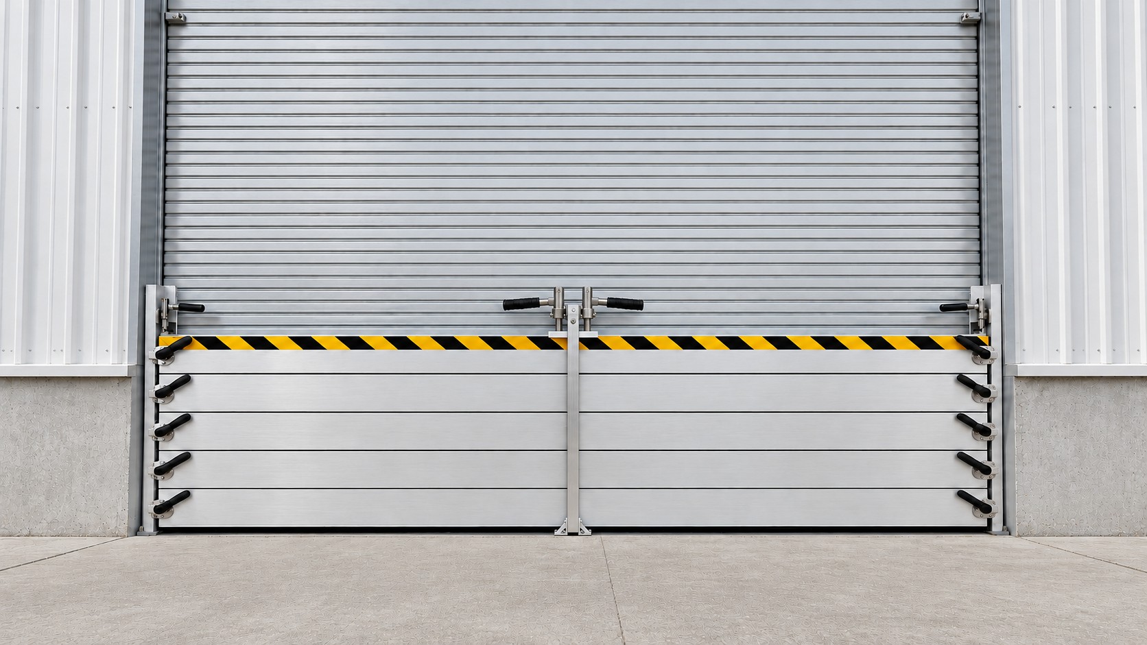
A > 3–6 m / B 3–6 m
Model A: width over 3 m to 6 m, height ≤ 1.0 m. Model B: width 3–6 m, height 1.2 m. The top compression post restrains panel movement at midspan, without intermediate posts or diagonal bracing.
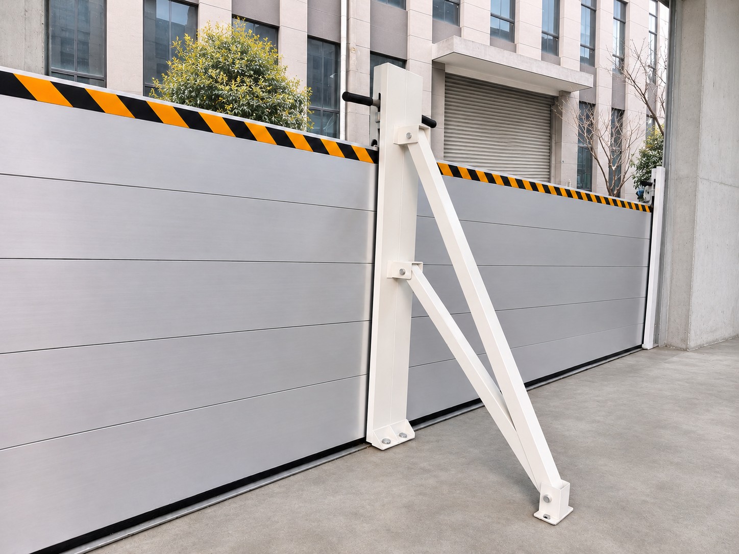
A > 6 m / B 3 m × 1.8 m
Model A: width over 6 m, height ≤ 1.0 m, subject to project review. Model B: width 3 m, height 1.8 m. Intermediate posts support panel spans; fit bracing and anchorage to the project drawings.
Images illustrate support arrangements only. Select dimensions from the model table and project drawings.
Dimensions or conditions outside the listed configurations require review. Engineering Judgment (EJ) support is a project-specific technical assessment, not a replacement for required testing, certification or approval.
MATERIALS AND COMPONENTS
High-strength stainless steel or carbon steel tracks with weather-resistant elastomeric seals provide edge restraint and sealing.
Lightweight aluminium alloy panels with a dedicated bottom sealing detail form the modular barrier face.
Dedicated side and top clamps mechanically secure the panels and compress the seals. Confirm supports, anchorage and fittings against the selected model and project drawings.
A storage rack keeps parts organised. Floor tracks and installation tools can be supplied to suit the project.
PERFORMANCE DOCUMENTATION
The revised catalogue lists static water, wave impact, water current and water retention after dynamic impact as review items. Verify leakage against the selected configuration and design flood height; check structural capacity at the design water level and confirm anchorage.
Use a valid report for the selected model, opening dimensions, design flood height and support configuration. The A/B revision supplies no detailed report or product certification document. This page does not infer PAS 1188-4 compliance, FM Approved status, BSI Kitemark certification or zero leakage. FD-02 FM approval does not extend to FH-01-A/B.
The catalogue describes suitability for humid, coastal and typical outdoor environments, with a main system design life ≥ 20 years. Assess materials, exposure and regular seal inspection and maintenance for the project.
INSTALLATION AND READINESS
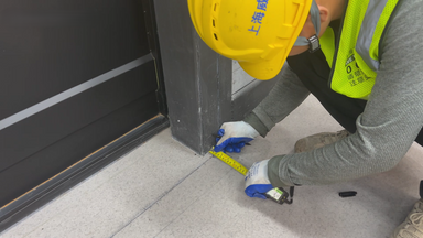
Measure and verify opening dimensions and installation positions.
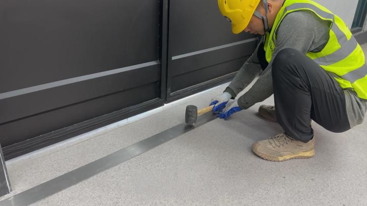
Recess and level the floor track. The catalogue specifies a level deviation ≤ 2 mm.
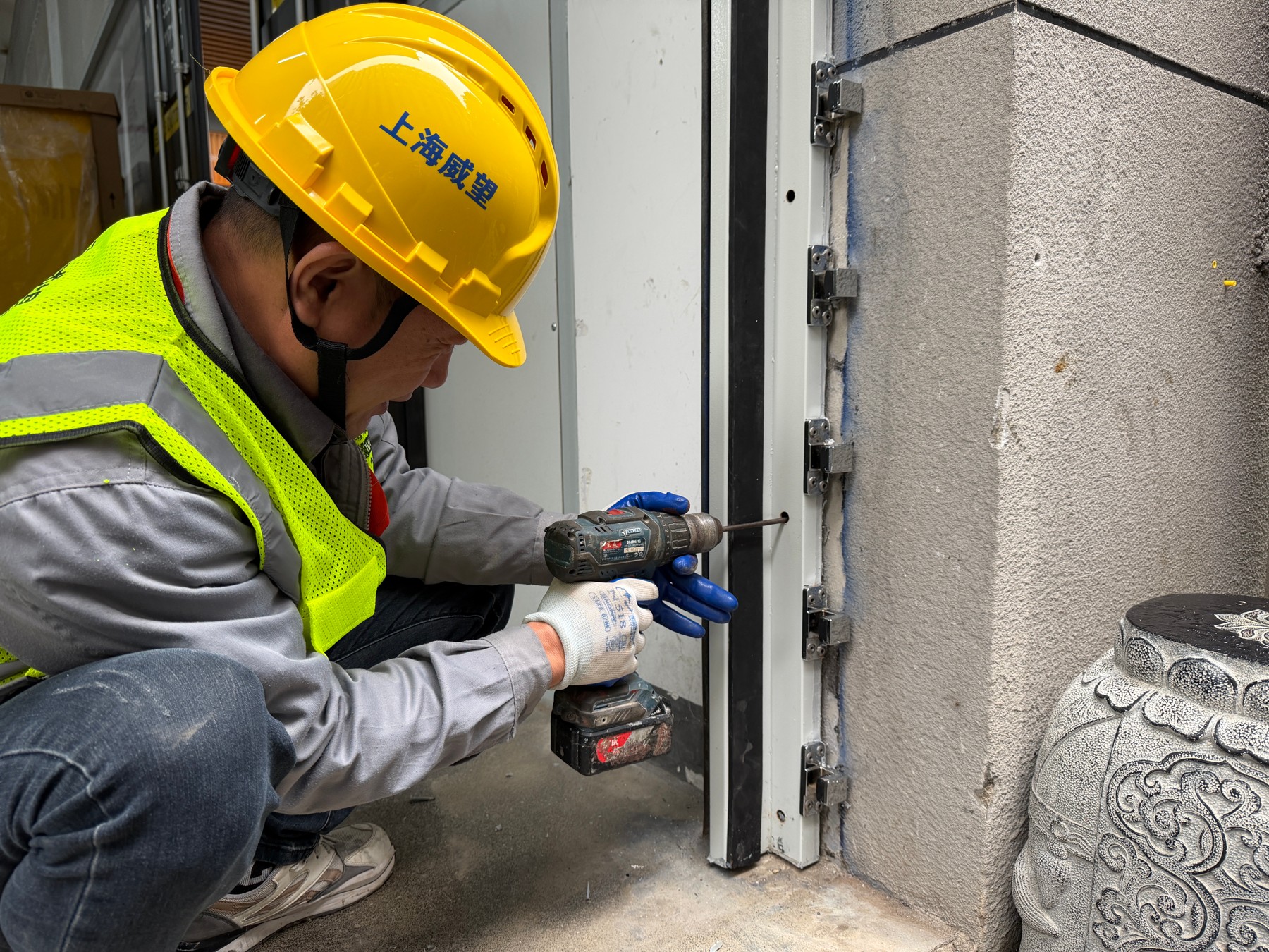
Anchor the wall tracks. Metal-clad walls require embedded steel tubes according to the catalogue installation detail; confirm the actual anchorage design.
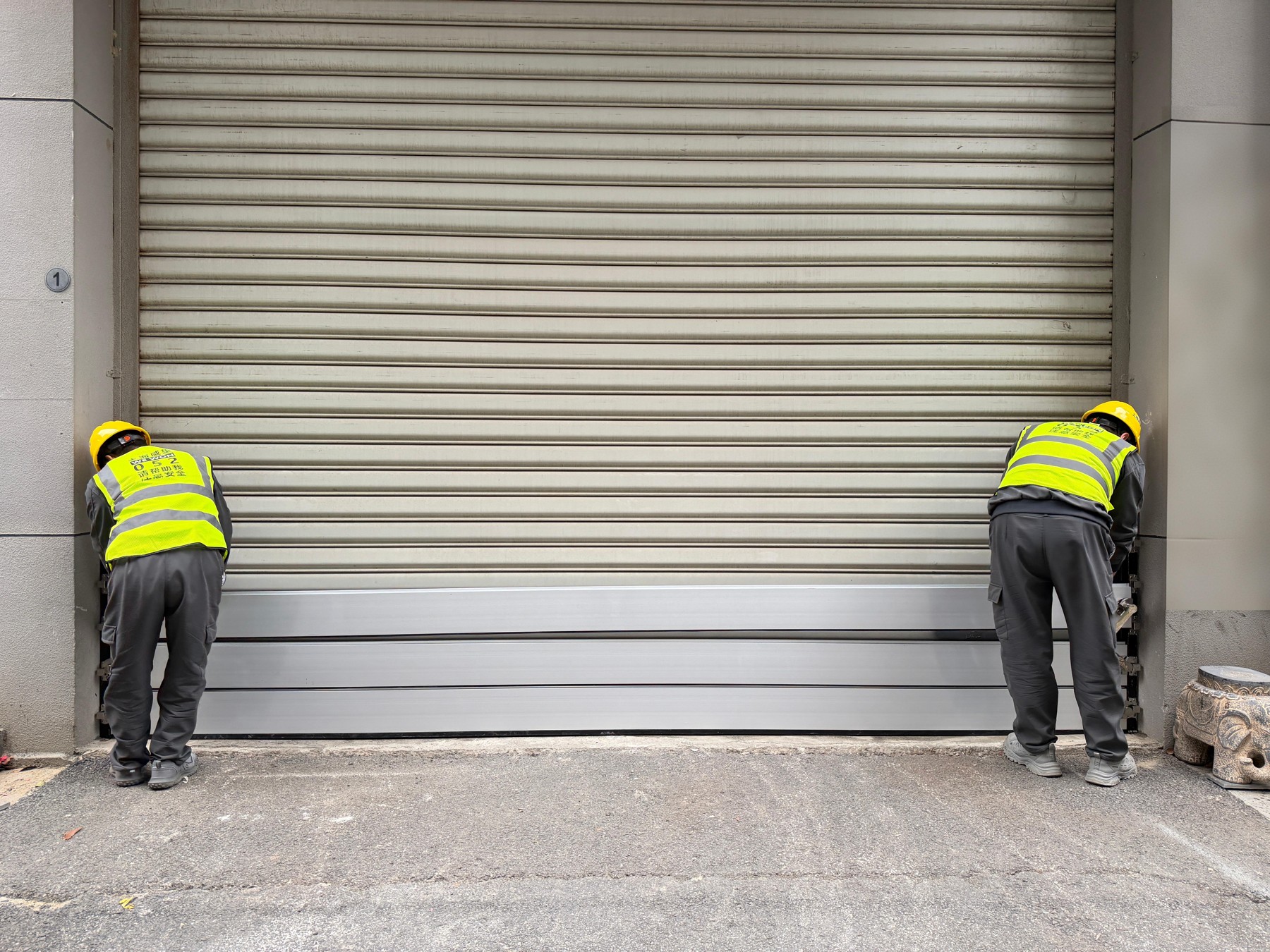
Stack the panels from bottom to top in numbered order.
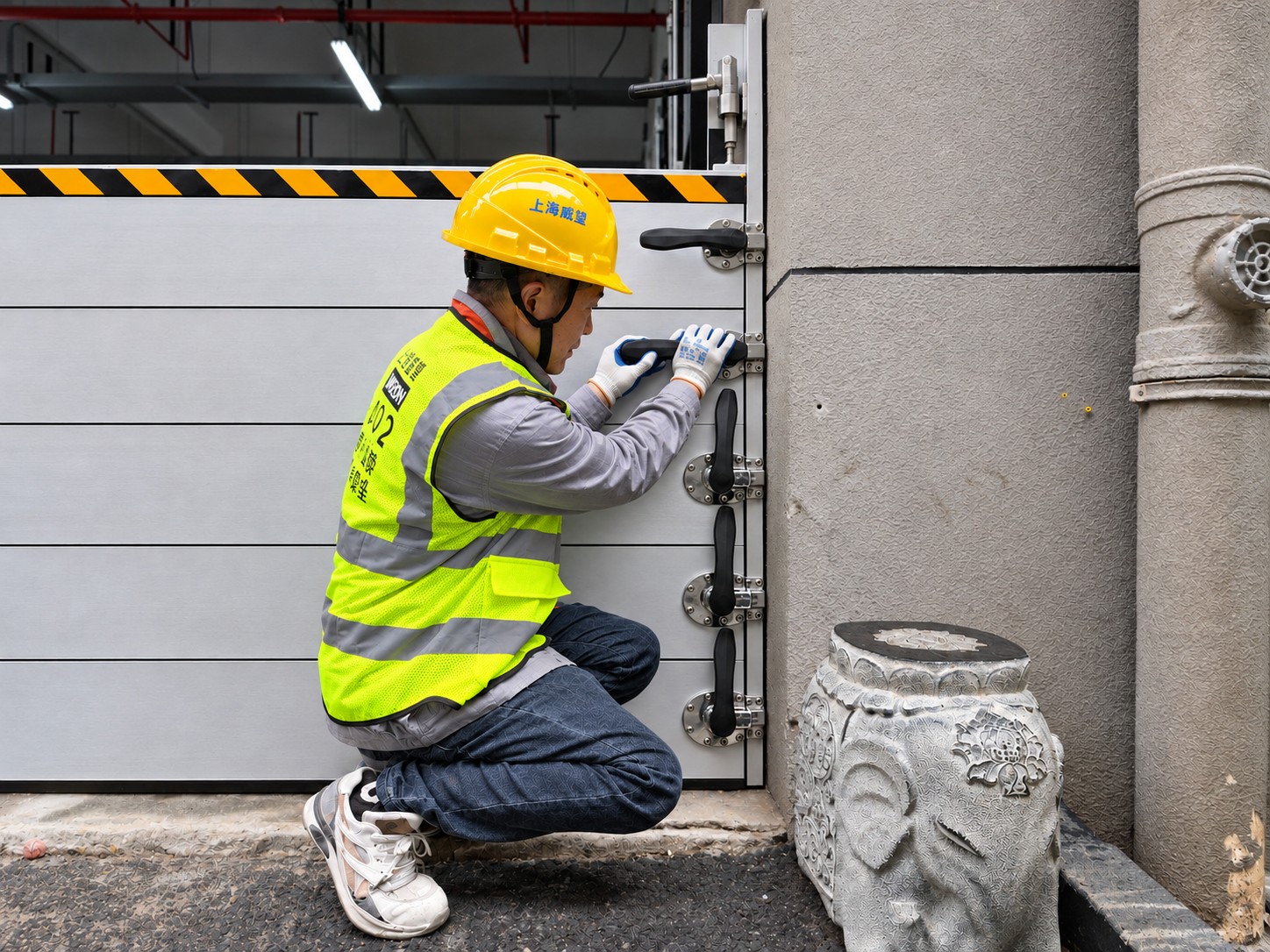
Use the lever bar to install clamps and fully compress the seals. Fit supports to the selected model and installation drawings, and check anchorage.
Fit supports per the selected model and installation drawings. Check anchorage.
APPLICATIONS
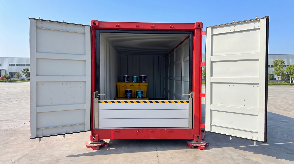
FH-01 provides flood protection around chemical-storage and battery energy storage system (BESS) containers, including entrances, equipment rooms and maintenance routes. These applications do not establish fire resistance, explosion protection or chemical containment performance.
SUPPLY AND SUPPORT
FAQ
Both belong to the FH-01 rapid-install clamp-lock flood barrier series, using mechanical clamps to secure aluminium alloy panels and compress EPDM seals. Model A lists design flood heights ≤ 1.0 m. Model B offers 1.2 m and 1.8 m configurations. Select supports as a matched model, clear width and design flood height.
For FH-01-A at design flood heights ≤ 1.0 m: width ≤ 3 m needs no supplemental support; widths over 3 m to 6 m use a top compression post; widths over 6 m use intermediate posts and diagonal bracing and require project review.
No. The revised catalogue requires valid performance reports for the selected model, dimensions, flood height and supports. It supplies no FM Approval, BSI Kitemark certificate or detailed report. The previous PAS 1188-4 reference cannot be assumed to apply to the revised A/B range, and FD-02 FM approval cannot be transferred to FH-01-A/B.
This page makes no zero-leakage guarantee. Check watertightness against the valid report and acceptance requirements for the selected model, dimensions, design flood height, supports and site sealing conditions. The revised catalogue supplies no universal leakage-rate value for all configurations.
The catalogue recommends monthly track cleaning and seal checks, annual moving-part lubrication and clamp inspection, and periodic water testing of seal integrity. A main system design life ≥ 20 years does not remove the need to maintain seals.
Provide clear opening width, design flood height, floor and wall construction, anchorage conditions, support and deployment space, drainage and water-flow conditions, storage arrangements and acceptance criteria. Select Model A or B, then check the listed configuration and valid performance documents. Other dimensions or conditions require project-specific review.
FH-01-B can use no supplemental support at a clear width of 3 m and design flood height of 1.2 m. The listed 3–6 m width at 1.2 m uses a top compression post. At 3 m width and 1.8 m height, an intermediate post and diagonal bracing are required; this is not a 3 m × 1.8 m unsupported configuration. Other dimensions or conditions require review.
No. The catalogue states main system design life ≥ 20 years, which differs from a commercial warranty term and seal replacement intervals. Actual service life depends on materials, exposure, installation and maintenance. Warranty terms are governed by the supply contract.
Send the clear opening width, target flood height and site drawings. We will help confirm the FH-01-A/B model, supports and performance documents required for the project.
Discuss your projectCatalogue project contact · Brian